The following information
has been reproduced from a post
to a thread on idle instability
issues on skylinesdownunder.co.nz
forums by 'phantom'. All credit
for this information goes to 'phantom'
and thanks for his permission to
reproduce here.
I'm having some technical
difficulties with my digital camera,
in particular focusing at close
distances! As such my attempts to
get a descent view of the AAC spool
etc. wasn't to good. I have instead
done an auto cad drawing of the
R33 AAC valve. Bear in mind that
this is a basic drawing for conceptual
purposes only!! It will however
give you a good understanding on
how it works. Additionally I've
also drawn a representation of my
new spool.
 |
What
does it look like?
- AAC Valve |
 |
| |
 |
|
 |
|
 |
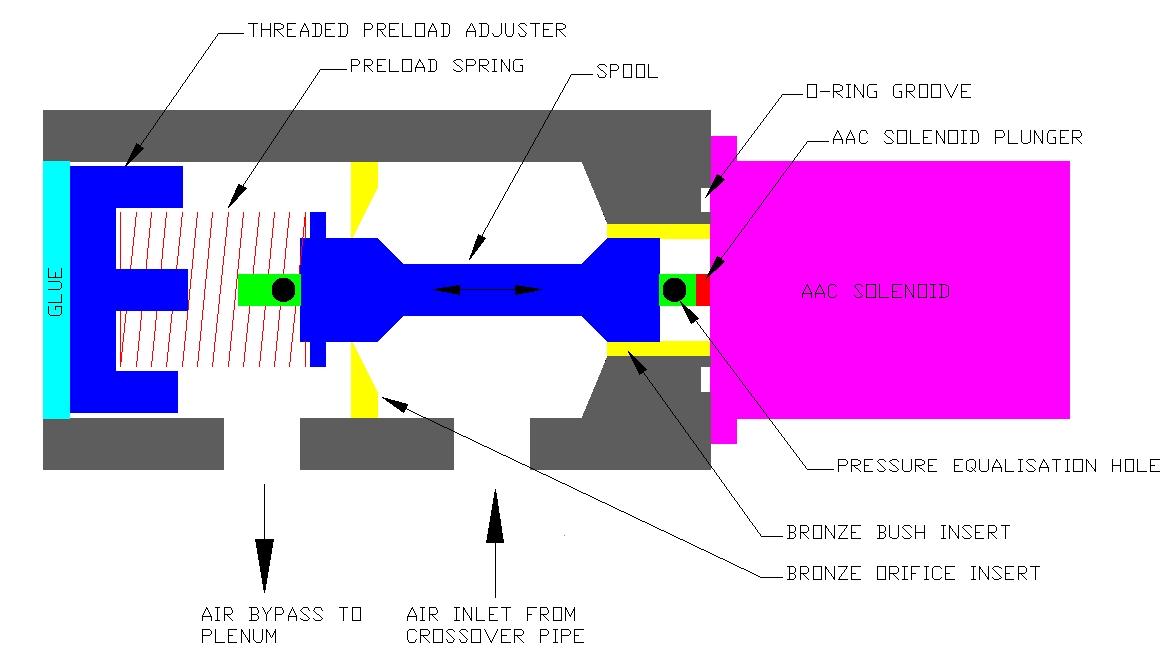
As states this drawing is a conceptual
interpretation of the inner workings
of the AAC and spool. The point
of wear on these things occurs on
the bronze bush insert on the right
and the bronze orifice insert on
the left. A loose spring will not
pre load the spool at all and it
will probably float around causing
irregular idle conditions. When
wear has occurred leakage through
the bronze orifice ensues even before
the taper section of the spool is
exposed.
This results in an AAC without a
significant airflow difference between
open and closed and anywhere in
between. Additionally, wear in the
bronze bush on the right causes
air to be sucked through the air
supply side, into the cavity enclosed
by the spool and the solenoid, and,
subsequently through the pressure
equalisation hole in the spool all
the way through to the other side
of the orifice and into the engine.
This leakage bypasses the spool
altogether. The spool has a hollow
steel tube at the centre to support
and guide everything.
The reason for it being hollow and
having a hole on each side is to
equalise the pressure on both sides
of the spool such that pressure
differences occurring as a result
of general engine running don't
cause the spool to move. Movement
can only be caused by the solenoid
plunger movement. This is typical
of this type of valve and I have
seen similar pressure equalisation
techniques in industrial hydraulic
and pneumatic proportional valves.
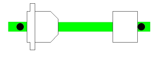
As the bush and orifice would be
difficult to manufacture I did the
next best thing and made a new spool
instead. I placed the spool in a
lathe and VERY GENTLY machined off
the plastic leaving the hollow central
tube. I then made the replacement
in three sections, purely out of
the difficulty in making such small
components with the size of cutting
tools I had available. The spring
retainer is straightforward and
can be very approximate in its sizing.
The taper section was then turned
down to a diameter measured with
an inside micrometer on the bronze
orifice hole. I made it slightly
larger and polished it to size whilst
in the lathe with some emery until
it JUST slid into the orifice without
binding. This took a few attempts
to get right. The bush end does
not need to have the taper as per
the factory. This is probably just
a manufacturing simplification.
It was simply a cylindrical section,
again referenced to the measurement
of the existing bush diameter as
measured with the inside micrometer.
I actually made it slightly longer
than standard as far as the equalisation
hole allowed on that side. The reason
being that the additional length
would assist in alignment once inserted
into the bush, and stop the tendency
for vibration to cause further wear.
All the sections had a 4 mm diameter
axially drilled hole on the lathe.
Accuracy is highly important, as
with close tolerances misalignment
will lead to the spool binding in
operation. I then slid the three
sections over the hollow tube, carefully
positioning the taper to the same
position as the original. The cylindrical
side placement was not as critical,
and simply slid far enough up to
the equalisation hole. I secured
these onto the hollow tube with
super glue. Don't laugh, but super
glue is designed for very close
fitting surfaces, and since the
4mm hole in the sections made a
nice sliding fit over the tube,
the super glue worked fantastically.
Placing the new spool back into
the body and blocking the relevant
holes then blowing through it revealed
almost zero leakage when closed.
Only once the spool was moved over
exposing the taper did significant
flow occur....just what the doctor
ordered!!
|
What
does it look like?
- Spool |
|
| |
 |
|
|
|
|
Next a new spring was found and
chopped and reshaped to the original
length but significantly lighter.
I wanted to maximise the movement
of the spool with the solenoid force
to amplify its effect on engine
RPM. As stated in the past the pre
load spring retainer is threaded
into the body and its depth can
be adjusted by turning the retainer.
The glue applied by the factory
over this was simply milled through
on a milling machine until I just
contacted the retainer. I then picked
out the remaining glue in the retainer
phillips head with a scriber. This
then allowed me to get a wide flat
blade screwdriver onto the retainer
and screw it out. The indentation
on the retainer is not exactly a
philips head but really a cross
with a circular centre. The factory
obviously has an automated tool
used for manufacturer adjustment
prior to glue sealing.
Once back together and on the car,
the engine was started and allowed
to reach temperature. I set the
RPM manually via the idle screw
to approximately 650 rpm so as to
not cause the solenoid to push out
the spool trying to compensate.
I then unscrewed the retainer until
the engine RPM JUST started to increase,
then turned it back in about a quarter
turn. This ensured that with the
given base duty cycle on the solenoid,
the resulting force had the spool
JUST about expose the taper. This
would guarantee that any further
increase in duty cycle by the ECU
would immediately expose the taper
and increase RPM rather than being
wasted just sliding the spool whilst
still on the straight portion in
the orifice.
As I've stated, once this was done,
the idle control returned with a
vengeance...and has been operating
beautifully now for about two weeks
straight. I resealed the pre load
adjuster with some silicone, as
there is slight leakage through
the thread. The silicone can be
easily pried out in future should
I need to readjust or disassemble.
Some may wonder why I bothered
with this. Well, this cost me nothing...a
new AAC costs $650. In addition
I had the advantage of adjustability
and therefore tunability to my specific
engine. A brand new one would remain
unadjustable.
Information
derived from 'phantom' at skylinesdownunder.co.nz
Information
on the page was last updated 10
July 2003
|